Product List
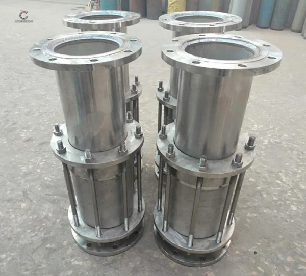
Monolithic Insulating Joint
Monolithic Insulating joint
1)Material: CS, SS AS
2)Size:1/2"-60"
3)Pressure: CLS 150-2500
4) ISO 9001:2008, ASME Certificate and U stamp
Monolithic Insulating joint
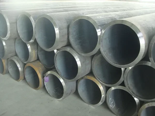
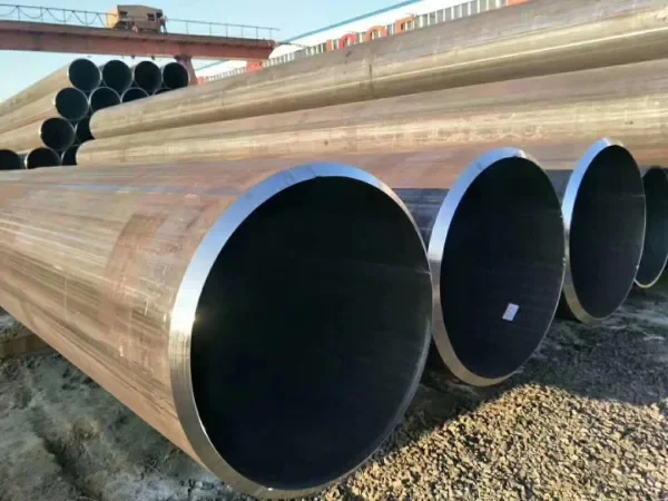
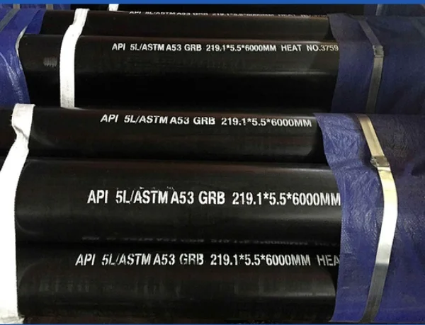
1, Pup material: API 5L Gr.B, X42, X46, X52, X56, X60, X65, X70
2, CL150,CL200,CL300,CL600,CL900,CL1500,CL2500
Monolithic Insulating joint Introduction:
The insulating joint (Isolating Joint) is the key component in Cathodic Protection (CP) System. It is mainly used in underground gas
transition and distribution system including gas reducing station, each section of the gas transition and distribution pipeline, also
the part between gas reducing station and the pipeline, which increases the life of the plant and equipment by reducing or
eliminating the electric and chemical corrosion damage.
Monolithic Insulating joint Specifications:
Ø Suitable for oil, city gas, natural gas, LNG, LPG, etc.
Ø Size: 1” to 60”
Ø Matching pipeline: API 5L Gr. B, X42, X52, X60, X65, X70, etc.
Ø Pressure rating: ANSI Class 150, Class 300, Class600, Class 900, Class1500, Class2500
Ø Ambient Temperature: -30°C-90°C
Ø Working Temperature: --20°C-120°C
Ø Standard Testing:
* Hydrostatic test: 1.5 times MOP (Max. Operation Pressure).
* Electrical Resistance: >= 20Mohm @ 1000v DC under dry air at 25 oC
* Dielectric voltage: >= 3.5kv AC 50Hz (1 minute) (Can be 5kv as per request)
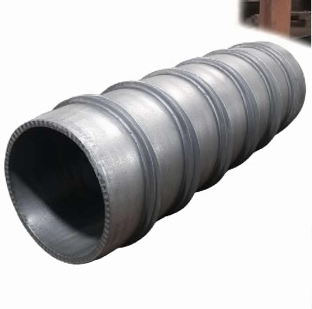
Detailed photos of Monolithic Insulating joint
The service life of the insulation joint: is the same as that of the pipeline; Applicable media: oil, gas, water, chemical raw materials, pulp applicable.
Quality requirements for insulation joints
Insulation strength: 2500V 50Hz 1 minute no breakdown or arc; Insulation resistance value: DC 1000V resistance value ≥6MΩ; Hydraulic test pressure: 1.5 times the design pressure; Airtight test pressure: equal to the design pressure; Non-destructive testing: According to JB4730-94, all butt joints are tested by 100% ray, and other pressure welds are tested by 100% magnetic particle. Groove: adopt API5L standard.
Construction and principle of insulating joint
The integral insulation joint consists of the following parts: upper pipe, lower pipe, sleeve, insulation parts, seals, and insulation coating. The insulation parts and seals are sandwiched between the upper and lower pipe butt ends of the insulation joint to form a double-sealing structure with insulation performance. The sleeve adopts two forms of groove welding or direct welding with the upper conduit, and the insulation parts and the upper and lower pipes are firmly wrapped in the inner surface, forming a "sealed container", which not only ensures a good insulation effect but also greatly improves the bearing capacity of the insulation structure.
Installation requirements for insulation joints
1. Avoid dead welding within 50 meters of the insulation joint installation place;
2. After the insulation connector is connected to the pipeline, it is not allowed to lift the pipeline within 5 meters of the connector;
3. Test the pressure of the insulation joint and pipeline instrument.
Advantages of a dual gasket system with insulated joints:
Without the need for precise surface finishing or special mechanical tolerances, the system can act simultaneously between two symmetrical forging surfaces and metal-insulated spacers, with each component working together to complete the seal.
The sealing parts with large cross-sectional areas can withstand a series of structural deformations caused by the action of pressure. Because of the large cross-sectional area of the sealing ring, the liquid must pass through a considerable distance before sideway leakage.
For this sealing system, all insulation pads are completely wrapped and will not deform when subjected to a sudden pressure drop.
As the pressure increases in the pipeline system, a balanced counterforce is generated in the sealing system to ensure that the force is balanced in the sealing system and the pressure circulation does not affect the sealing system.


